





In industrial chemical processing, water treatment, petrochemical refining, and mineral processing, liquid-solid separation represents a core operational unit. Industrial processes rely on pressure leaf filters to clarify liquid streams, recover valuable solid catalysts, and remove insoluble impurities. The performance of these closed pressure vessels depends heavily on the design and structural integrity of the internal Liquid Filter Leaves.
Operating under dynamic fluid pressures and varying liquid viscosities, liquid filter leaves must balance two opposing engineering demands: providing high hydraulic permeability to maximize filtrate throughput while maintaining a sharp, reliable particle retention threshold. Furthermore, these leaves must endure cyclic differential pressures ($\Delta P$), resist aggressive chemical corrosion from acids or alkalis, and maintain flat, unbowed structural profiles over thousands of operating hours.
When substandard filter leaves are used, fluid turbulence, mesh sagging, and frame distortion often occur. These issues lead to uneven filter cake distribution, premature pressure drop spikes, and unfiltered slurry bypass into clean effluent lines.
This technical article provides an in-depth engineering analysis of liquid filter leaves, examining fluid mechanics within multi-layer mesh packs, structural frame reinforcement, precision spigot sealing, and operational maintenance protocols for industrial liquid filtration systems.
To explore foundational metallurgy, weave structures, and primary filtration mechanics across our complete product family, visit our core [Stainless Steel Filter Leaf].
Hydraulic Permeability and Multi-Layer Mesh Architecture
The primary function of a liquid filter leaf is to allow clean liquid to pass freely into its internal drainage core while trapping suspended solid particles on its exterior screen faces. Achieving optimal hydraulic permeability requires careful selection of the mesh layer stack.
Fluid Dynamics Inside the Filter Pack
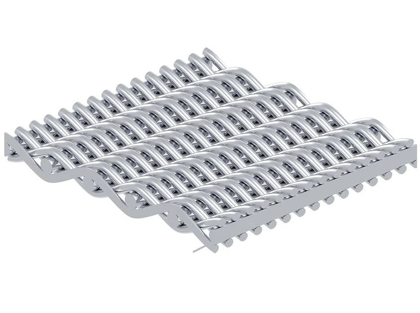
● Active Outer Filtration Layers: The outer screens typically utilize Plain Dutch Weave (PDW) or Twill Dutch Weave (TDW) wire cloth ($10\,\mu\text{m} - 150\,\mu\text{m}$). The tight, triangular fluid passages capture suspended solids on the surface while creating a stable bed for pre-coat materials like diatomaceous earth or perlite.
● Intermediate Drainage Support Screens: Positioned directly beneath the active outer screens, intermediate square mesh layers prevent the fine outer mesh from pressing into the heavy central core under hydraulic pressure. This preserves open flow channels across the entire panel face.
● Central Heavy Drainage Grid: The innermost core consists of a heavy-gauge square wire mesh ($1.2\text{mm} - 2.5\text{mm}$ wire diameter). This core provides wide, uninhibited internal drainage channels that guide clean liquid toward the bottom or central discharge spigot with minimal hydraulic head loss.
Structural Frame Integrity and Deflection Control Under Liquid Loads
As solid particles accumulate on the exterior faces of a liquid filter leaf during a filtration cycle, differential pressure across the panel gradually rises. Under heavy wet cake loads or sudden pump surges, filter panels are subject to substantial mechanical stress.
Preventing Structural Deflection and Frame Warping
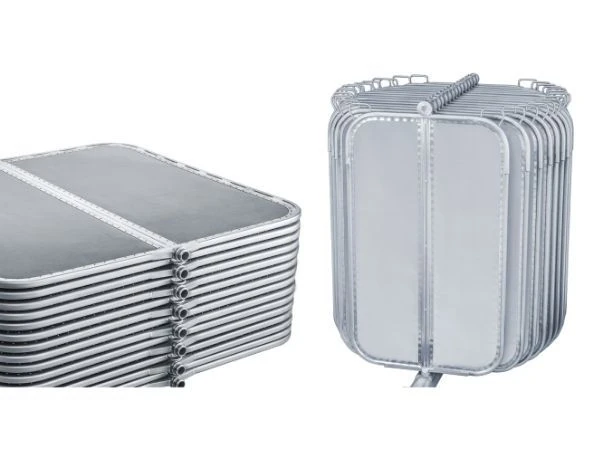
● Heavy Cold-Formed C-Channel Profiles: The outer rim of the filter leaf is constructed from heavy-gauge stainless steel C-channels. This shape provides a high section modulus, resisting bending forces that cause leaf edges to bow inward under high differential pressures ($\Delta P > 3.5\text{ bar}$).
● Continuous Perimeter TIG Fusion Welding: Outer wire mesh layers are continuously TIG-welded along the inner channel rim. This full-penetration weld locks the mesh sheets under uniform planar tension, eliminating loose mesh flexing that causes fatigue failure along frame margins.
● Internal Structural Ribs: For large filter panels ($>1800\text{mm}$ in length), internal solid stay bars are integrated across the central drainage grid to tie the opposing mesh faces together, preventing outward panel bulging during backwash cycles.
Spigot Fluidics and Manifold Bypass Prevention
The discharge spigot located at the bottom or center of the filter leaf serves as the sole exit point for clean filtrate entering the vessel collector manifold. A compromised spigot seal allows raw, unfiltered liquid to bypass directly into clean effluent storage tanks.
CNC Precision Machining and Sealing Engineering
| Sealing Feature | Standard Commercial Leaf | Precision Liquid Filter Leaf | Engineering Advantage |
| Spigot Fabrication | Welded tubing / Light casting | CNC Solid Bar Stock Machining | Exact roundness and tight tolerance |
| O-Ring Configuration | Single elastomeric ring | Dual O-Ring Recesses | Double barrier against raw fluid bypass |
| Gasket Selection | Standard NBR Rubber | FDA Viton / EPDM / PTFE | Chemical & thermal degradation resistance |
| Manifold Alignment | Loose positioning pin | Precision CNC Alignment Lug | Prevents tilting during vessel insertion |
Cake Discharge Dynamics: Wet Sluicing vs. Dry Vibratory Drop
Depending on process requirements, liquid filter systems discharge accumulated filter cake using either wet sluicing or dry pneumatic vibration.
● Wet Sluice Discharge: In wet discharge systems, oscillating spray nozzles blast high-pressure liquid across the outer mesh faces. The calendered, smooth surface of our Dutch weave screens reduces surface adhesion, allowing wet cake to wash off quickly and minimizing rinse water consumption.
● Dry Vibratory Discharge: In dry cake recovery systems, compressed gas dries the cake before pneumatic vibrators strike the leaf array. The rigid, monolithic frame transfers shockwaves directly to the outer screens, causing the dry filter cake to crack and drop cleanly into the discharge hopper.
Maintenance and Inspection Best Practices
To maintain high hydraulic flux and prolong the service life of liquid filter leaves, plant engineers should follow structured maintenance routines:
● Periodic Chemical Cleaning (CIP): Remove scale and organic buildup by circulating dilute acid or alkaline cleaning solutions through the filter vessel. Ensure that cleaning chemicals match the metallurgical limits of the leaf alloy (e.g., SS316L or Alloy 20).
● Ultrasonic Bath Regeneration: Blinded or scaled leaf panels can be immersed in heated ultrasonic cleaning tanks to dislodge deeply embedded fine particles from the inner Dutch weave wire intersections without damaging the mesh structure.
● Regular Spigot O-Ring Replacement: Inspect spigot O-rings during every turnaround. Hardened, swollen, or worn O-rings should be replaced immediately to maintain leak-free manifold operation.
Conclusion
Liquid Filter Leaves engineered with heavy-gauge C-channel frames, high-flow 5-layer drainage architectures, and precision CNC-machined spigots provide the hydraulic capacity, solid retention, and mechanical strength required in demanding liquid processing applications. Selecting robust, precision-built filter leaves prevents slurry bypass, lowers operating pressure drops, and extends service life across industrial process lines.
To review general vertical pressure leaf designs and bottom spigot fluidics, read our technical article on [Vertical Leaf Filter Elements: Bottom-Discharge Fluidics, Vessel Manifold Sealing, and Array Alignment Stability], or contact our engineering team for custom liquid filter leaf CAD drawings and commercial inquiries.
Related Articles
1. Weave Mechanics, Surface Calendering, and Particle Retention Optimization
2. Structural Integrity, Pre-Coat Filtration Mechanics, and Cycle Optimization
3. Top/Bottom Discharge Engineering and Heel Recovery
4. Engineering Arc Rigidity, Shell Contouring, and Cake Stability
5. Mechanical Stress Mitigation and Frame Architecture in Pressure Filter Leaves