





In industrial solid-liquid separation, vertical and horizontal pressure leaf filters serve as the primary workhorses for high-volume clarification loops. Operating across edible oil refineries, chemical processing plants, high-temperature molten sulfur units, chlor-alkali facilities, and pharmaceutical refining, these pressure vessels rely entirely on internal stainless steel filter leaf elements to maintain filtrate clarity and sustain high daily volumetric throughput.
However, procuring replacement pressure leaf elements can be a complex and unforgiving technical process. Procurement managers, maintenance engineers, and plant operations leaders frequently navigate a confusing matrix of wire mesh weave patterns, metallurgical alloy selections, internal drainage grid designs, and precise nozzle geometries. Choosing an incorrect specification leads to catastrophic operational consequences: rapid mesh blinding, frame warping inside vessel racks, edge-bypass leakage, filtrate turbidity spikes, and frequent, unscheduled plant shutdowns.
This ultimate buyer's guide breaks down the complete engineering roadmap for specifying, sizing, and procuring high-performance stainless steel pressure leaf elements. By following these structured, step-by-step criteria, plant technical teams can eliminate guesswork, lower Total Cost of Ownership (TCO), and secure high-reliability replacement hardware engineered to match exact operational demands.
To benchmark the baseline manufacturing tolerances, frame squareness standards, and metallurgical options that form the structural foundation of long-life filter elements before beginning the specification process, visit our primary [Stainless Steel Filter Leaf] pillar page.


Step 1: Evaluating Process Fluid Parameters & Alloy Selection
The first critical step in defining a pressure leaf specification is conducting a thorough metallurgical and fluid dynamic audit. Operating temperature, pH levels, dissolved gas content, chloride concentration, and fluid viscosity determine the exact alloy grade and internal core layout required to prevent corrosion failure and mechanical fatigue:
A. Edible Oils & Food-Grade Processing
● Operating Conditions: Temperatures up to 120°C, presence of free fatty acids, bleaching clay, and phosphatides.
● Alloy Standard: Stainless Steel 316L is the industry benchmark. It provides comprehensive food-grade compliance, excellent resistance to fatty acid corrosion at elevated temperatures, and high mechanical ductility to endure repeated pneumatic vibrator cycles during cake discharge.
B. High-Temperature Molten Sulfur Loops
● Operating Conditions: Extremely tight temperature windows between 135°C and 145°C, high density, and severe risk of sulfur solidification if temperatures drop.
● Alloy Standard: Requires thermally stabilized alloys such as SS 316L, SS 904L, or Alloy 20. The outer U-channel frames must be engineered with thermal-expansion relief clearance to prevent structural frame bowing when transitioning between ambient and high-operating temperature states.
C. Aggressive Acid Loops & Chlor-Alkalis
● Operating Conditions: Low pH environments, high salt concentrations, and high chloride exposure.
● Alloy Standard: Standard SS 304 or SS 316L fails rapidly under these conditions due to severe pitting and Stress Corrosion Cracking (SCC) along border weld zones. These demanding applications mandate premium nickel-chromium alloys like Hastelloy C276, Monel 400, Alloy 20, or Titanium Grade 2 to guarantee structural resistance against chemical degradation.
Step 2: Active Surface Mesh Selection & Layer Architecture
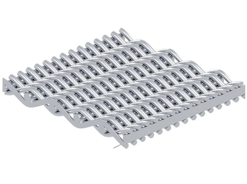
Matching the active wire mesh weave to your slurry's target Particle Size Distribution (PSD) is essential to achieve zero-bypass liquid clarity while preventing rapid surface pore blinding and premature pressure buildup:
A. Coarse & Heavy Earth Applications
● Process Targets: Bleaching earth removal in edible oil refining or heavy inorganic slurry filtration with particle sizes greater than 15 microns.
● Mesh Architecture: 24x110 Plain Dutch Weave. This configuration utilizes robust warp and weft wire diameters that create rigid, stable pore openings. It delivers rapid liquid flux rates, supports fast initial cake formation, and allows quick, clean cake release during vibration cycles.
B. Fine Polish & Light Oil Clarification
● Process Targets: Dewaxing, winterization, and fine polishing loops capturing particulates between 10 and 15 microns.
● Mesh Architecture: 30x150 Plain Dutch Weave. This mesh strikes an optimal balance between micro-particle interception and low clean-side pressure drop ($\Delta P$), ensuring crystal-clear filtrate output over extended batch runs.
C. Sub-Micron & Catalyst Recovery
● Process Targets: Precious metal catalyst recovery, active pharmaceutical intermediate separation, and fine chemical filtration capturing particles under 5 microns.
● Mesh Architecture: Reverse Plain Dutch Weave (RPDW). Featuring high-density warp wires packed tightly on the active filtration face, RPDW creates a dense micro-matrix capable of trapping sub-micron solids under high pressure without suffering pore deformation.
Structural Layer Upgrade: 3-Layer vs. 5-Layer Matrices
For high-pressure or heavy-duty batch cycles, plant engineers should specify an advanced 5-Layer Structural Matrix rather than a basic 3-layer layout. In a 5-layer design, fine outer filtration skins are supported by intermediate fine-mesh drainage layers and a heavy central crimped core. This multi-stage support prevents the active filtration mesh from sagging ("nesting") into the drainage grid under high pressure drops (△P > 4.5Bar), effectively doubling the element's fatigue life and preserving uniform flow channels.
Step 3: Critical Dimensional Verification & Nozzle Geometry
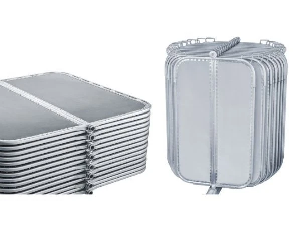
To guarantee a seamless, drop-in replacement that installs effortlessly into existing filter vessels without binding or requiring physical modification, engineering teams must verify three primary structural measurements prior to ordering:
A. Overall Panel Height & Panel Width
Measure the exact outer boundaries of the U-channel frame. When specifying replacement leaves, mandate a strict diagonal squareness tolerance of ≦2.0mm (the difference between Diagonal 1 and Diagonal 2 across the frame corners). Out-of-square leaves twist inside the vessel, binding against the internal guide tracks, damaging vessel racks, and failing to transfer vibration energy cleanly during cake discharge.
B. Nozzle Neck Geometry & Sealing Mechanism
Inspect the outlet nozzle connection carefully. Determine whether your vessel utilizes a top-discharge or bottom-discharge configuration. Verify whether the neck sealing surface relies on a flat gasket face, a machined O-ring groove, or a double O-ring spigot. A dimensional misalignment of even a single millimeter at the nozzle junction will break the seal, allowing raw slurry to enter the clean filtrate manifold.
C. Vessel Guide Track Spacing & Panel Flatness
Measure the outer U-channel frame thickness and verify that total panel bow (out-of-flatness tolerance) does not exceed 1.5mm across the entire panel face. Uncontrolled panel bowing causes adjacent filter leaves to rub against each other inside the vessel bundle, scraping active mesh faces and causing localized mechanical tears.
Step 4: Quality & Manufacturing Integrity Check
To protect your facility from substandard generic aftermarket parts, verify that your manufacturer integrates these four mandatory engineering controls into their production process:
● Continuous 360° Automated Robotic Welding: Intermittent spot welds or mechanical crimping leave microscopic perimeter gaps that expand under pressure, creating edge-bypass leakage. A continuous 360° robotic weld permanently fuses the U-channel frame and mesh layers into a single, hermetic structure.
● Positive Material Identification (PMI) Verification: Require mill test reports and direct PMI laser spectrographic verification for every batch of stainless steel wire and sheet metal to ensure compliance with specified alloy chemistry.
● Precision Calendered Mesh Finish: Ensure the outer filtration mesh undergoes precision mechanical calendering. Calendering flattens the knuckles of the woven wires, creating a smooth, uniform planar surface that promotes effortless cake release and prevents abrasive scraper damage.
● Re-Screening Compatibility: Ensure the U-channel outer frame is constructed from heavy-gauge stainless steel. Rigid frames can be refurbished, re-trued, and fitted with new mesh packs in future maintenance cycles, lowering long-term replacement hardware costs by up to 45%.
To review how professional frame re-screening can lower your annual maintenance budget while retaining structural frames, see our detailed technical guide on [Hermetically-Sealed Multi-Layer Stainless Steel Filter Leaves].
Technical Audit Checklist for Plant Maintenance Teams
Before issuing a Purchase Order (PO) for replacement filter leaves, evaluate your vendor and technical specification against this mandatory checklist:
● Tolerance Standard: Does the supplier explicitly guarantee a frame diagonal squareness tolerance of ≦2.0mm?
● Perimeter Seam Inspection: Are boundary welds specified as a continuous 360° automated TIG weld, or are they using spot welds?
● Mesh Surface Preparation: Is the active filtration mesh hydraulically pre-tensioned and calendered prior to frame assembly?
● Drawing Approval: Will the manufacturer provide serialized CAD approval drawings verifying nozzle dimensions, overall height, width, and guide track clearances before beginning production?
Conclusion
Procuring high-performance replacement pressure leaf elements requires a balance of metallurgical verification, precise dimensional measurement, and strict manufacturing standards. By moving away from generic aftermarket parts and specifying laser-trued, robotically welded assemblies tailored to your specific fluid dynamics, your plant can permanently eliminate edge-bypass leakage, optimize batch cycle times, and achieve the lowest Total Cost of Ownership (TCO).
Whether you are replacing worn elements in an existing Amafilter, Sharplex, Sparkler, or Niagara vessel, upgrading your process to zero-bypass Reverse Plain Dutch Weave, or seeking custom engineering drawings for a new installation, review our high-clarity technical breakdown on [Custom-Engineered Premium Pressure Leaf Filter Elements] or contact our technical sales team today for a comprehensive engineering evaluation.