





In the challenging realm of continuous industrial process engineering, fluid throughput and filtration cycle efficiency are the twin metrics that dictate overall plant profitability. When processing high-viscosity liquids or temperature-sensitive compounds-such as molten sulfur in sulfuric acid plants, crude palm oil during winterization, concentrated sugar syrups, or hot petrochemical resins-the physical laws governing fluid flow change dramatically. In these critical loops, the goal is always to maximize the volume of clarified filtrate produced per square meter of filter area before the system hits its terminal differential pressure (△P). When filtration cycles run short, requiring frequent backwashing, cake dumping, and system resets, the entire production line suffers from costly operational bottlenecks.
When searching for the root cause of sluggish flow rates and rapid pressure spikes in these viscous applications, plant managers typically look at chemical parameters, adjusting flocculant dosing, altering pre-coat slurry concentrations, or blaming fine particle migrations. However, deep-dive fluid dynamic investigations frequently reveal a purely mechanical and thermodynamic culprit: Internal Hydraulic Resistance coupled with thermal degradation within the replacement leaf assemblies.
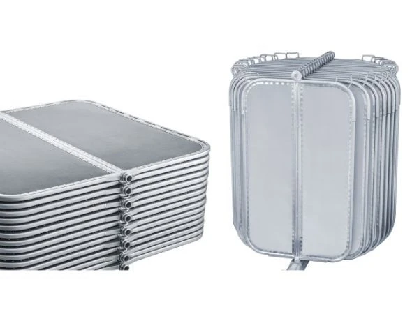
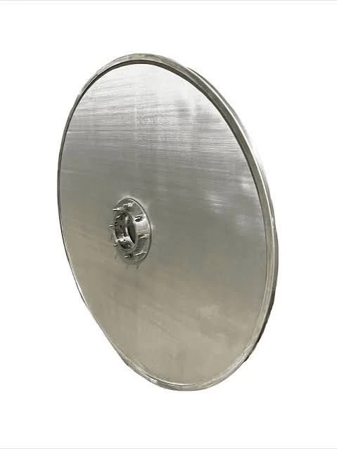
A pressure leaf filter element is not merely a piece of wire cloth wrapped around a metal frame; it is a complex, engineered multi-layer fluid and thermal transport system. If the internal mesh layers are poorly configured, over-compressed, or selected without precise consideration for temperature-dependent viscosity, the element itself acts as a severe hydraulic restriction. Before diving into the microscopic physics of layer-to-layer fluid migration, you can benchmark our complete manufacturing engineering standards, structural frame tolerances, and raw material mill certifications on our primary [Stainless Steel Filter Leaf] pillar page.
Understanding Fluid Drag and Mechanical Deflection under High Viscosity
To understand why standard replacement filter elements fail in high-viscosity and high-temperature service, we must look at how viscous fluids behave when forced through compressed metal meshes under pressure. Unlike thin, watery liquids, high-viscosity fluids generate immense frictional drag at the micro-level as they pass through the filtration boundary.
In standard leaf elements, the internal mesh layers are often tightly and unevenly compressed during frame assembly. When the process pump ramps up, the high mechanical pressure of the viscous flow forces the fine outer filtration mesh to push directly into the coarser support layers behind it.
This physical phenomenon-known as mesh nesting-creates highly restricted, high-shear micro-channels. For high-viscosity fluids, these collapsed pathways act like tight bottlenecks. The resulting fluid drag causes an immediate, artificial spike in differential pressure ($\Delta P$), forcing the system to terminate the batch long before a full, healthy filter cake has had the chance to build on the outer face.
Technical Parameter Matrix: Viscosity and Thermal Flow Benchmarks
To avoid internal hydraulic restrictions and thermal-drop viscosity spikes, procurement and engineering teams must evaluate specific structural and thermal characteristics of the interior mesh layers. The following table highlights the critical engineering parameters required to secure low-drag, high-flux performance over extended operating cycles under challenging viscosity conditions:
| Process & Material Parameter | Standard Multi-Layer Leaf | Our Viscosity-Optimized Elements | Test / Verification Method |
| Max Process Viscosity Limit | Under 100cP (Low-viscosity only) | Up to 3,000cP (Highly viscous) | Brookfield Viscometer Profiling |
| Optimal Operating Temp | Up to 110℃ (Standard Seals) | Continuous up to 280℃ (High-Temp) | Thermal Cycling Chamber Test |
| Internal Layer Sequence | Standard 3-Layer layout | Advanced 5-Layer or 7-Layer Matrix | Physical Layer-by-Layer Audit |
| Thermal Conductivity ($k_{th}$) | Low (Air gaps/loose contact) | High (Pre-Tensioned Solid Contact) | Thermal Imaging Laser Analysis |
| Internal Core Open Area | Under 45% (Restricted space) | ≧ 68% Hydro-Optimized Open Grid | Digital Area-Fraction Calculation |
| Pressure Drop ($\Delta P$) Build | Exponentially rapid increase | Linear, Controlled Progression | Differential Pressure Logging |
| Mesh Compression Deflection | ≧2.5mm under 4.0Bar load | ≦0.4mm (Zero-nesting stability) | High-Pressure Laser Profilometry |
The Threat of Cold Spots and Internal Crystallization
For temperature-sensitive fluids, the thermodynamic behavior of the replacement leaf is just as important as its mechanical strength. In applications like molten sulfur filtration (where the fluid must be kept within a strict window of 135°C to 145°C to prevent extreme viscosity spikes or solidification), any localized drop in temperature inside the leaf panel is catastrophic.
If cold process liquid is pumped into a filter vessel during startup, or if the internal drainage grid of a leaf does not transfer heat efficiently from the steam jacket, "cold spots" will develop on the leaf face. When the hot, viscous fluid hits these cold spots, its viscosity spikes instantly.
In the worst cases, the target compound begins to crystallize and solidify directly inside the fine pores of the 24x110 Plain Dutch Weave skin or within the internal drainage grid. Because this crystallization occurs inside the element, standard pneumatic vibrating or backwashing cycles cannot dislodge it. The element becomes permanently blinded from within, requiring complete removal and expensive thermal burn-out or chemical cleaning.
To prevent this, our Warp-Resistant Flat-Surface elements are fabricated with a focus on thermal stability. If your plant is struggling with chronic temperature-drop blinding, rapid pressure spikes, or internal crystallization, explore our full engineering specifications on our dedicated [Warp-Resistant Flat-Surface Pressure Leaf Filter Elements] page to see how our thermal-stabilized layer configurations prevent localized cold spots.
Engineering the Drainage Core for Viscous Fluid Clearance
Once a viscous fluid successfully passes through the active outer filtration skin, it must be evacuated from the leaf core as quickly as possible. If the filtrate pool stagnates inside the leaf, it will cool down, causing its viscosity to rise and creating a localized backpressure zone that slows down the surrounding filtration area.
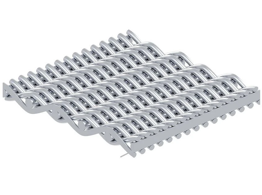
Our premium elements overcome this by utilizing an ultra-heavy, high-tensile 3x3 or 4x4 crimped stainless steel wire grid featuring a massive wire diameter up to 1.60mm. This provides a wide, unyielding internal channel that allows viscous fluids to flow toward the discharge nozzle with minimal resistance.
Many budget suppliers replace this robust crimped grid with cheap, thin expanded metal sheets. Under the intense mechanical loads of a long filtration run with heavy, viscous slurry, these thin sheets flex and bow inward under the weight of the heavy cake. When the central drainage core flattens, the internal flow channel is constricted, trapping the viscous fluid inside, causing a rapid spike in differential pressure, and forcing an early shutdown of the batch.
By utilizing our unyielding crimped wire grid, the internal drainage channels remain completely open, guaranteeing maximum flow space and constant fluid velocity under all operational pressures.
Eliminating the Nozzle Exit Restriction
The final bottleneck for viscous fluids occurs at the outlet nozzle where the clarified liquid exits the leaf and enters the manifold. If the outer frame channel is welded directly to the nozzle without fluid bypass reliefs, the high-viscosity liquid is forced to transition from a wide, flat panel into a narrow circular tube through a sharp, unoptimized angle. This sudden contraction causes high shear stress, localized turbulence, and a severe pressure drop.
Our high-permeability elements feature precision engineering at the frame-to-nozzle junction. The outer heavy-gauge stainless steel U-channels are custom-machined with internal fluid bypass ports and relief slots directly at the base of the discharge neck.
This custom design ensures that viscous liquid flowing from the edges of the panel can transition into the outlet nozzle smoothly. By eliminating this final exit restriction, we lower the total system pressure drop, prevent internal solids accumulation at the frame borders, and maintain an uninterrupted flow profile from the filter face directly into the clean filtrate tank.
Technical Audit Checklist for Plant Procurement Teams
To ensure your next batch of replacement filter leaves provides maximum fluid throughput and minimal internal resistance in high-viscosity or high-temperature service, specify these three core benchmarks in your procurement documents:
● Thermal Contact Certification: Ensure the multi-layer mesh pack is hydraulically pre-tensioned and framed under high mechanical compression to secure uniform heat transfer across the entire face.
● Aperture Stability Under Load: Require the supplier to verify that the intermediate support meshes prevent the active filtration skin from nesting or deflecting by more than 0.4mm under peak operating pressures.
● Internal Core Open Area: Mandate a minimum internal core open area of 65% to ensure viscous liquids have a low-resistance path to the outlet nozzle.
Conclusion
Processing high-viscosity and high-temperature fluids requires replacement hardware designed with a deep understanding of fluid dynamics and thermodynamics. Settling for cheap, standard replacement leaves built with loose screens, thin expanded metal cores, and unoptimized frames is a guaranteed way to inject high hydraulic resistance into your processing loop. This results in short cycles, rapid pump wear, and reduced plant capacity. By upgrading to engineered elements where precise multi-layer sequencing, high-open-area crimped cores, and thermally conductive frame designs work together, your plant can permanently eliminate internal flow restrictions, achieve extended batch cycle times, and maximize your liquid clarification efficiency.
If your technical team is currently troubleshooting a sudden drop in processing flux, experiencing rapid pump pressure spikes, or looking to prevent permanent internal pore blinding, review our comprehensive diagnostics on our dedicated 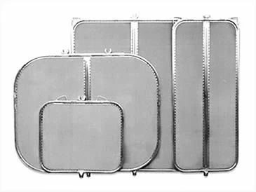 maintenance analysis page, or contact our engineering team directly to submit your process parameters for a custom thermodynamic quote.