






The accuracy of a filtration system is only as reliable as the instruments used to verify its specifications. In industrial environments, where a deviation of a few microns can lead to system-wide contamination or mechanical failure, selecting the appropriate measurement tool is a critical engineering decision. Measuring the "mesh size" or "aperture" of a filter is not a one-size-fits-all task; a tool perfectly suited for a heavy-duty mining screen would be utterly destructive if applied to an ultra-fine 500-mesh pharmaceutical grade cloth. Consequently, professionals must match the instrument's precision, contact force, and magnification capabilities to the physical properties of the filter media being inspected.
This guide provides a technical review of the top five most essential tools utilized in the field and laboratory for measuring filter mesh. We will move from basic mechanical devices used for coarse identification to advanced automated vision systems that represent the cutting edge of Industry 4.0. Beyond simply listing hardware, we will explore the calibration requirements, the potential for human error (such as parallax or over-compression), and the specific use cases where each tool excels. By understanding the limitations and strengths of these instruments, quality control managers and maintenance technicians can ensure that their filtration infrastructure meets the most stringent international standards for accuracy and reliability.


Digital Micrometers: The Foundation of Wire Measurement
Precision in Wire Diameter Verification
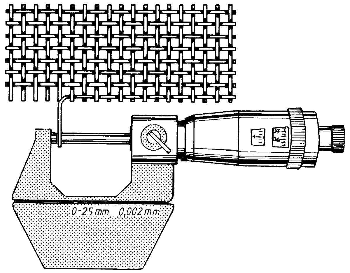
The digital micrometer is the indispensable "first tool" in mesh analysis. Before calculating the aperture or mesh count, one must know the exact wire diameter (d). A high-quality micrometer provides a resolution of 0.001 mm (1 micron), which is essential because the wire diameter directly dictates the open area of the filter. When inspecting a mesh, the micrometer measures the thickness of individual strands, allowing engineers to verify if the manufacturer used the correct gauge of wire as specified in the Mill Test Report (MTR).
The Role of the Ratchet Thimble
A common measurement error when using micrometers on fine mesh is "over-compression." If the operator applies too much force, the micrometer can slightly crush or flatten the wire, leading to an artificially low diameter reading. Professional-grade micrometers are equipped with a "ratchet thimble" or "friction thimble." This mechanism ensures that a consistent, repeatable amount of pressure is applied to the wire every time, eliminating user-to-user variability and ensuring that the measurement is non-destructive.
Calibrating for Zero-Error Accuracy
Micrometers are sensitive instruments that can drift due to temperature changes or mechanical wear. To maintain accuracy, they must be "zeroed" before every session. In a laboratory setting, they are verified using NIST-traceable gauge blocks. For filter mesh measurement, ensuring the measuring faces (the anvil and spindle) are perfectly clean is vital; even a microscopic speck of dust or oil can result in a 5-10 micron error, which would significantly skew the subsequent calculation of the mesh aperture.
Professional Linen Testers (Optical Loupes)
Fixed-Focus Magnification for Manual Counting
The linen tester is a specialized, folding magnifying glass that has been the industry standard for counting mesh for decades. Unlike a standard handheld magnifying glass, a linen tester has a fixed base that maintains a perfect focal distance from the lens to the mesh. Most industrial linen testers provide 10x magnification and feature a built-in scale (usually 1 inch or 25.4 mm) at the base. This allows a technician to count the wires per inch with high stability and minimal optical distortion.
Avoiding Parallax and Spherical Aberration
The primary challenge with manual counting is "parallax error"-the perceived shift in an object's position when viewed from an angle. To use a linen tester correctly, the eye must be positioned directly above the center of the lens. Higher-quality testers use "achromatic" or "aplanatic" lenses to prevent spherical aberration (blurring at the edges), ensuring that the wires at the start and end of the 1-inch scale are just as sharp as those in the middle.
Field Use vs. Laboratory Use
While linen testers are excellent for field identification of mesh counts between 10 and 150, they become difficult to use for meshes finer than 200. The human eye struggles to distinguish individual wires at such small scales, even with 10x magnification. In these cases, the linen tester serves as a "quick-check" tool to verify that the correct roll of mesh has been delivered, while the final certification is left to more powerful digital inspection systems.
Digital Calipers: Versatility for Large Apertures
Measuring "Space Cloth" and Large Openings
For coarse filters, often referred to as "Space Cloth" in the mining and aggregate sectors, digital calipers are the preferred tool. These instruments are designed to measure the "clear opening" (the aperture) directly. Because these openings are often 5 mm or larger, the sharp jaws of the caliper can easily be inserted between the wires. Digital calipers allow for rapid switching between metric and imperial units, making them versatile for international projects.
The "Inside Measurement" Challenge
When using calipers to measure mesh apertures, the technician must use the "inside" jaws (the smaller teeth on the top of the tool). It is essential to ensure that the jaws are perfectly parallel to the wires. A slight tilt can result in a measurement that is larger than the actual aperture. For more accurate results on medium-mesh screens, it is recommended to measure across 10 openings and divide by 10, rather than relying on a single measurement point.
Limitations on Fine Mesh and Soft Materials
Digital calipers are not suitable for fine mesh (above 100 mesh) because the jaws are too blunt to fit accurately into the microscopic gaps. Furthermore, because calipers require physical contact, they can easily deform soft mesh materials like copper, brass, or thin-gauge synthetic polymers. If the mesh "bows" under the pressure of the caliper, the resulting reading will be inaccurate. In these scenarios, non-contact optical tools must be prioritized.
Digital Microscopic Inspection Systems
High-Definition Imaging and Software Analysis
As filtration moves into the sub-50 micron range, digital microscopes become mandatory. These systems utilize high-resolution CMOS sensors to project a magnified image of the mesh onto a computer monitor. Integrated software allows the user to "click" on wire edges to calculate aperture, wire diameter, and even the "warp/shute ratio" automatically. This eliminates the eye strain associated with linen testers and provides a digital record (screenshot) for quality compliance folders.
Automated Aperture Mapping
Advanced digital microscopes can perform "Aperture Mapping," where the software identifies every single opening in the field of view and generates a statistical distribution of the sizes. This is critical for high-stakes applications where the "Maximum Individual Opening" is just as important as the average. If a 100-micron filter has a single 120-micron hole due to a weaving defect, the automated system will flag it immediately, whereas a manual count would likely miss it.
Depth of Field and 3D Inspection
Some high-end digital microscopes offer "3D Stitching" or "Focus Stacking." This is particularly useful for inspecting Dutch Weaves or Sintered Multi-layer Mesh, where the wires exist on different planes. By capturing images at different focal depths and merging them, the software creates a sharp, three-dimensional model of the filter's internal path. This allows engineers to measure the "tortuosity" and "effective pore size" of complex filter structures that appear as a blur under traditional magnification.
Optical Comparators (Shadowgraphs)
Non-Contact Silhouette Measurement
The optical comparator is the "gold standard" for non-contact measurement in a laboratory setting. It works by projecting a magnified silhouette of the mesh onto a large circular glass screen using a high-intensity light source. Because the tool uses light to create the image, there is zero physical contact with the mesh, making it the perfect tool for ultra-fine, delicate, or precious-metal filters that must remain pristine.
Using Digital Readouts (DRO) for Absolute Precision
Operators use a Digital Readout (DRO) system to move the comparator's stage. By aligning a crosshair on the screen with the edge of one wire and then moving it to the next, the system calculates the exact distance (the pitch) to within 0.0001 mm. This level of precision is required for certifying test sieves according to ASTM E11 or ISO 3310-1 standards. It allows for the measurement of the "average aperture" across a statistically significant sample of the mesh roll.
Verifying Weave Uniformity and Angle
Beyond simple dimensions, optical comparators allow technicians to check the "squareness" of the weave. By rotating the screen's protractor, the operator can measure the angle between the warp and shute wires. If the weave is not perfectly 90 degrees (known as "skewing"), the shape of the apertures changes from squares to parallelograms, which alters the filtration characteristics. The large-format screen of the comparator makes these structural irregularities easy to spot and quantify.


Tool Comparison and Selection Matrix
Matching the Tool to the Mesh Count
Selecting the right tool depends primarily on the mesh count and the level of certification required. Heavy industrial screening can be managed with calipers and rulers, while pharmaceutical and aerospace filters require the precision of optical comparators and digital microscopy.
Mesh Measurement Tool Selection Matrix
| Tool | Ideal Mesh Range | Measurement Method | Precision | Portability |
| Digital Micrometer | All (Wire Dia) | Contact | 0.001 mm | High |
| Linen Tester | 10 - 150 | Visual/Manual | 0.1 mm | Excellent |
| Digital Caliper | 2 - 60 | Contact | 0.01 mm | High |
| Digital Microscope | 100 - 635 | Optical/Non-contact | 0.0005 mm | Low |
| Optical Comparator | 20 - 500 | Shadow/Non-contact | 0.0001 mm | Stationary |
Common Errors and Tool-Specific Solutions
Every tool has a potential "fail point." Understanding these errors is essential for accurate data collection.
Common Errors and Corrective Actions
| Tool | Common Error | Technical Impact | Solution |
| Micrometer | Over-tightening | Thinner wire reading | Use the ratchet thimble |
| Linen Tester | Parallax | Miscount of wires | View perpendicular to lens |
| Caliper | Jaw Tilting | Larger aperture reading | Ensure jaws are parallel |
| Microscope | Poor Contrast | Edge detection failure | Adjust backlighting/threshold |
| Comparator | Improper Focus | Blurred silhouette | Use high-magnification lenses |
Maintenance and Calibration Protocols
Ensuring NIST Traceability
To stand up to a quality audit, every tool must be calibrated using standards traceable to the National Institute of Standards and Technology (NIST). For mechanical tools like calipers and micrometers, this involves "Gauge Blocks." For optical tools, "Calibration Slides" with etched chrome lines of known dimensions are used. Without a current calibration certificate, any measurement taken is technically "unverified" in a regulated industry.
7.2 Cleaning and Environmental Control
Industrial dust and oil are the enemies of precision measurement. Micrometer faces must be cleaned with lint-free paper before every use. Optical lenses on linen testers and microscopes should be cleaned with specialized lens tissue and isopropyl alcohol to prevent "ghosting" or obscured images. Furthermore, because metal expands with heat, critical measurements should always be taken in a temperature-controlled environment (ideally 20°C) to prevent thermal expansion from skewing the results.
Conclusion
Final Recommendation for Industrial Users
Accurately measuring filter mesh size is a technical process that requires a combination of high-quality hardware and disciplined methodology. As we have reviewed, there is no single "best" tool; rather, there is a "correct" tool for every specific application. For rapid field checks, the linen tester remains king. For verifying wire diameter, the digital micrometer is unmatched. And for the extreme precision required by modern high-tech industries, digital microscopy and optical comparators provide the non-contact, high-resolution data necessary for total quality assurance.
Investing in the right suite of measurement tools-and the training to use them correctly-prevents the catastrophic costs of using the wrong filter mesh. Whether you are preventing a "contaminant bypass" in a fuel line or ensuring the uniformity of a pharmaceutical powder, the precision of your instruments is the foundation of your process safety. In the world of industrial filtration, where the microscopic becomes macroscopic in terms of impact, accurate measurement is the ultimate safeguard.
To see how these specific tools integrate into a global filtration measurement strategy and the mathematical formulas required to process their data, return to our core technical manual:
[How to Measure Mesh Size of Filter]